Guide to wire a 4 wire AC motor(4 wire ac motor wiring diagram)

To translate electrical energy into mechanical motion, AC motors are frequently employed in a wide range of commercial, industrial, and domestic applications. The 4-wire AC motor stands out among the various types of AC motors because of its adaptability, effectiveness, and wide range of uses. This thorough article intends to provide you with a detailed overview of the correct wiring of a 4-wire AC motor, assuring its reliable and effective performance.
Understanding the Basics of AC Motors
The unseen workhorses that power many of our modern conveniences and industrial processes are AC motors. These amazing machines turn electrical energy into mechanical motion, which drives fans, pumps, conveyor belts, and so much more. Let’s first become familiar with the simple fundamentals of AC motors before delving into the specifics of wiring a 4-wire AC motor.
Let’s Keep it Current: AC vs. DC
Imagine a river of charged particles flowing as electricity. Direct Current (DC) and Alternating Current (AC) operate similarly to two different rivers within this one. The topic of our conversation, AC, oscillates back and forth, occasionally changing course. Contrarily, DC moves steadily in a single direction. While DC is like a steady, quiet stream, AC is like the ebb and flow of waves. As implied by their name, AC motors are powered by electrical current that is changing direction.
Magnetic Magic: Creating Motion from Current
Have you ever heard of a magician making an object vanish and reappear? AC motors pull off a similar ruse using both motion and power. A magnetic field is produced by an electrical current passing through a coil of wire in this trick, which is known as electromagnetic induction. The coil spins as a result of this field’s subsequent interaction with another magnetic field. Utilizing this spinning motion, the motor-connected equipment is propelled.
Components of a 4-Wire AC Motor
Consider a 4-wire AC motor as a straightforward puzzle with essential elements. Here are those components:
Stator: This is the part of the motor that is stationary and contains the wire coils that produce the magnetic field.
Rotor: The moving component intended to rotate inside the stator is known as the rotor. Your motor moves when the magnetic field pulls on it, causing it to begin dancing.
Run and Start Windings: These resemble the muscles of a motor. The rotor is propelled into motion by the start winding, while the run winding maintains its steady motion.
The common wire, which carries power to and from the motor, functions as the network’s major thoroughfare.
Safety first with ground wire!
Amass Your Materials
Make sure you have the following equipment and supplies available before you begin:
- a four-wire AC motor
- flat-head and Phillips screwdrivers
- Wire strippers
- Wire nuts
- Voltage tester for electrical tape
- (Optional but recommended) Wire labels
Safety First
Turn off the power: To protect your safety while working, turn off the power at the circuit breaker before you begin.
Wear proper protective equipment such as insulated gloves and safety goggles for your safety.
Identify Motor Wires
(4 wire ac motor wiring diagram)
For AC single phase 4 wires motor has 4 wires each of which is colored a particular way Black, Blue, Yellow, and White or Black/Yellow, Blue/Yellow, Black and Blue (Figure 1)and Black,Blue, Yellow, and White(Figure 2 ). To verify the color codes, refer to the owner’s manual.
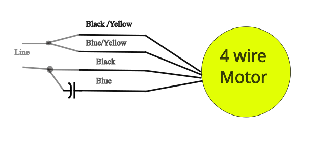
Figure 1:4 wire ac motor wiring diagram

Figure 2:4 wire ac motor wiring diagram

Figure 3:4 wire ac motor wiring diagram
For AC 3 phase motors normally have four wires(in the market 4-wire(L1.L2.L3 and N(figure 4)), 3-wire(L1, L2, L3) and 5-wires(L1, L2, L3, N, and E, Here we explain about” 4 wire AC motor wiring”)), each of which is colored a particular way. These hues could be Black wire in phase one.
Second phase: red wire, Third phase: blue wire. The white wire is neutral. To verify the color codes, refer to the owner’s manual.
.

Figure 4:4 wire ac motor wiring diagram
Wiring Method
For single phase motor
Refer Figure 1, figure 2, and Figure 3 to connect wires. For the majority of motors, the order is irrelevant; however, if there are any special instructions, see the manufacturer’s manual.
Ground Wire of power supply (Green): Attach this wire to the motor’s grounding termination point. This wire is in charge of ensuring security, preventing electrical shock, and it needs to be linked firmly.
For 3 phase motor
Refer Figure 4 to connect wires. For the majority of motors, the order is irrelevant; however, if there are any special instructions, see the manufacturer’s manual.
Ground Wire of power supply (Green): Attach this wire to the motor’s grounding termination point. This wire is in charge of ensuring security, preventing electrical shock, and it needs to be linked firmly.
Secure Connections
Securely tighten the wire connections to the terminals using a screwdriver to tighten the terminals. It’s possible for loose connections to create performance issues or even dangers.
Insulate Exposed Wires: After attaching the wires, cover the terminals with electrical tape to add insulation and avoid any unintentional contact.
Examine the wiring
Turn ON power: After ensuring that all connections are solid, Turn ON the power at the circuit breaker.
Voltage Test: To determine whether the motor is receiving the proper voltage, use a multimeter(Voltage tester). This step is essential to make sure the motor runs effectively and safely.
Troubleshooting
Double-check all of your connections if the motor won’t start or is acting strangely. The issue could be brought on by faulty or loose wiring.
Consult the manual: If you’re having problems, check the manual for the motor or ask a professional for help.
Conclusion
Wiring a 4-wire AC motor need not be difficult. These detailed instructions will help you wire your motor safely and effectively. Always put safety first, check your connections, and refer to the owner’s instructions as necessary. You can quickly get your AC motor up and running with the proper strategy.
FAQs
What are the 4 wires on an electric motor?
Induction motor with a single phase and an inbuilt capacitor:
(A capacitance meter will be able to detect internal capacitance because only one wire is continuous to the case and the other two have low resistance between them.) Connect a variac to non-ground wires, then increase the voltage until it begins to turn. That is likely only half of the maximum voltage.
The three-phase induction motor
(In all three combinations, the resistance between any two pairs of wire is the same; there is no connection to the ground.) Wires should be connected to L1, L2, and L3. Start with a lower three-phase voltage if you are unsure of the operating voltage. Try the next higher voltage if it is sluggish and draws a lot of currents. You are coming close if the motor accelerates quickly and has a reasonably low current when unloaded. Too much voltage will cause the device to accelerate quickly and consume a lot of current even when there is no load. Turn it off or watch it burn.
What do L1 and L2 mean on an electric motor?
The wires L1 and L2 lead to and from the power source. The hot wire is L1. It delivers 120V to the parts. The neutral wire is L2. 120V is returned to the source by it.
Why are there 4 wires on a single-phase motor?
A unidirectional single-phase motor has how many wires? Neutral and live, at least two. If it is reversible, at least four because the start capacitor and winding are connected independently by the reversing switch. If it is made to adjust to different voltages, it might have more.